

INTRODUCTION
The isolated power converter has a rich history of bringing modern, complex, efficient, and SAFE electronics to fruition. It is important to focus on the key characteristics of a power converter that dictate isolation properties. They drive many of the leading factors that go into today’s cutting-edge power supplies by maintaining Moore’s Law on the load side while optimizing the manufacture, cost, and reliability of critical components such as magnetics and driving other advanced packaging techniques on the supply side.
A Brief Overview of Isolated DC/DC Converters
The isolated DC/DC converter has enabled countless applications that would not otherwise be possible. Some prominent examples are medical power supplies, high-speed communication buses, offline power solutions, motor drives, and high-voltage use cases.
Additionally, one could argue that the most valuable contribution of isolated DC/DC converters relates to the isolation itself. Being able to SAFELY process high voltages and/or large amounts of power has been a critical contribution of power electronics to society. Many people may not be aware of all of this and therefore do not have an appreciation for these enabling technologies, but I am sure they are happy with the results in their daily lives. As power electronics engineers (or related), we are very much accustomed to being the unsung heroes that “secretly” make all the electronics of the world operate, even if considered “black magic” or unbeknownst to the user.
First, we should define what isolation is and how it applies to DC/DC converters. Electrical (a.k.a. – galvanic) isolation is the physical separation of conductors to prevent the direct flow of current between them [1]. The quickest test for evaluating if any level of isolation is present in a system is to evaluate the ground potentials between two targets. The grounds between isolated circuits should be at inde- pendent (a.k.a. floating) potentials. In addition to safety needs, there are several practical uses of floating grounds in DC/DC converters, which will be covered a little later.
Power conversion circuits use many different types, methods, and implementations of isolation, so we shall quickly overview the most salient here. The classification of isolation depends completely on the physical isolation techniques, they are often accomplished in the transformer assembly/construction and by physical spacing. The table below showcases a more comprehensive overview of isolation in DC/DC converters and their implementation.
| Isolation grade class | Description | Example use case |
|---|---|---|
| Functional | The output is isolated, but there is no protection against electric shock | 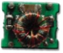 Ring Core Transformer with Functional Isolation |
| Basic | The isolation offers shock protection as long as the barrier is intact | 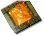 Bobbin Transformer with Basic Isolation |
| Supplementary | An additional barrier to basic, required by agencies for redundancy | 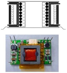 Example of a Reinforced Transformer Construction with a Basic and Supplementary Layer of Insulation (shown as the thick black lines in the diagram |
It is very important to note that the requirements and aspects of isolation needs are dictated by many different industrial/safety stan- dards, which can be highly dependent on the application and/or geographical location of usage. So be sure to capture any safety/certifi- cation requirements for your system early in the design process. It is imperative to research the specific requirements of the application at hand as the metrics, spacings (in 2D & 3D), isolation levels, and verification test methodology/setups can vary greatly and often be the difference maker between a smooth development and unexpected cost/time budget overruns. For instance, please see the excerpt below for the voltage spacing requirements of uninsulated conductors from IPC-9592B. While it clearly calls out minimum spacing based on con- ductor potentials, it also notes that creepage/clearance requirements in a related standard (IEC 60950 in this case) may be more stringent and precedence should be taken. Supporting a medical and/or high-reliability application will also come with many application-specific guidelines/requirements in this regard.

While isolation is commonly accomplished in transformer construction, it can also be implemented in other ways, particularly for smaller signals (i.e., control feedback, digital communications, etc.). It is very common to isolate communication buses, such as that of CAN-bus in automotive and industrial applications by using a small, isolated DC/DC or even capacitive isolation for digital signals. The small-signal feedback information from an isolated power converter’s output can be fed back to the input via an optoisolator. The optoisolator converts a signal’s electrical energy to optical, then back to electrical, thus passing along the critical control info while preserving the galvanic isolation between input and output.
Modern improvements in transformer construction/materials, 3D power packaging (3DPPR) techniques, and other novel geometries and manufacturing processes have made great strides in this space. Higher levels of reinforced insulation along with improved assembly techniques enable a design to meet isolation requirements, while still shrinking the overall size of the solution and utilizing the benefits of more automated manufacturing processes. This enhances overall quality and reliability, while concurrently taking advantage of economies of scale so that the robustness and power density improvements do not come at the detriment of cost. A prime example is how previously manually-wound toroids are now automatically controlled by implementing a planar structure that embeds windings in printed circuit boards (PCB) and directly incorporates the magnetic core materials into the surrounding geometry.
Impacts of Isolation on Converter Design

The most common figures of merit (FOM) regarding the design and optimization of power solutions are their size, weight, and power (a.k.a. SWaP factors). When combined with a cost metric, this can also be referred to as SWaP-C factors [4]. Given the different methods and levels of isolation, a design may require, these support needs can have big impacts on overall SWaP-C factors, particularly in filter components. Most systems cannot ship without signoff/certification for meeting (sometimes) multiple safety and functional standards so these are not “nice to have” kind of solutions, but are critical to market as well as inject cost and time into a project development schedule that did not account for the resources required to support these contingencies.
For instance, the table in the last section demonstrates the tradeoff in voltage versus spacing needs when packing conductors at different potentials into tight spaces. The class of isolation grade determines how many isolation protection features must be present and their minimum characteristics (i.e., in terms of material, thickness, and/or redundancy) for meeting the isolation spec (typically conveyed in terms of voltage level and withstand time for an exposure to such voltage(s) to still be functionally viable). This translates into a very typical tradeoff analysis between wanting to shrink overall solutions for optimizing SWaP, yet also coming at the detriment of cost when more expensive components (such as triple-insulated wire or TIW) can help to meet requirements in more compact arrangements.
Other technical factors such as thermal mitigation and supporting wide, high-voltage ranges may drive the compactness of a solution. Like any engineering development, reasonable compromises need to be made between meeting the core, functional/safety requirements of the system, cost impacts to development schedules/budgets, warranty/reliability needs, and time-to-market (TTM) targets. Given mag- netics manufacturing remains among the last manual component assembly needs on the line, it should be reiterated that relegating as much of that to automation and non-hand-soldered assembly as possible can help optimize many of the most crucial elements of optimiz- ing SWaP-C and improving reliability in a design.
At this point, it seems prudent to provide a quick mapping of isolated solutions to common power topologies and implementations. While a comprehensive topology overview is beyond the scope of this paper, this is meant to give a brief overview of which power conversion topologies support isolation and why.
| TOPOLOGY | FUNDAMENTAL CIRCUIT | IMPACTS OF ISOLATION/REGULATION |
| UNREGULATED PUSH-PULL (ROYER) | 
Unregulated Push-Pull Converter Circuit |
< Vout > OR < Vin
< Two Switches < Isolated Topology < Saturable-core Transformer < Low-cost for Higher/Lower/Inverted/Bipolar Outputs < Use with Unregulated Input |
| INVERTING BUCK-BOOST (FLYBACK) | 
Basic Flyback Converter Circuit |
< Vout > OR < Vin
< Single Switch < Isolated Topology < Higher Efficiency for Lower Power, Very Robust (energy stored in transformer) < Most Common Offline Power Supply, Can Be Regulated or Unregulated |
| HALF-BRIDGE (PUSH-PULL) | 
Basic Half-Bridge Converter Circuit |
< Vout > OR < Vin
< Two Switches < Isolated Topology < Higher Efficiency for Higher Power < Utilizes half line cycle for energy extraction/commuta- tion < Can Be Regulated or Unregulated |
| FULL-BRIDGE | 
Basic Full-Bridge Converter Circuit |
< Vout > OR < Vin
< Four Switches < Isolated Topology < Highest Efficiency for Higher Power < Utilizes full line cycle for energy extraction/commuta- tion < Can Be Regulated or Unregulated |
| FORWARD | 
Basic Forward Converter Circuit |
< Vout > OR < Vin
< Isolated Topology < Higher Cost, Higher Efficiency, Complex Magnetics Assembly < Best for Highest Efficiency & Power Scaling, But Com- plex Control < Can Be Regulated or Unregulated |
A natural and very common question to ask is about when to apply what topology and determine the appropriate level of isolation (if any) required by the application. Unfortunately, there are no direct answers because so many factors driving decisions are highly dependent on the use case, SWaP-C targets, and safety needs. There are even applications in which isolation is used to simplify the production of certain voltage outputs, irrespective of any safety isolation. Taking advantage of the floating ground can easily enable an inverted output, a higher output, or multiple outputs as shown in the figure below.

Figure 2: Non-safety Applications for Isolated Solutions, From “Understanding isolation in DC/DC converters” Blog [2]
Systems that provide external inputs/outputs in the way of ports, wires, and direct tissue exposure (such as with some medical equipment) are common candidates for isolated power solutions. The requirements to support high-speed communications concurrent with power lines (universal serial bus or USB, Power over Ethernet or PoE, etc.) may come with specialized needs for multiple ground potentials, stringent isolation to protect end users, and/or maintaining data and power integrity over physically-long busses. Even in very low-power applications, the use of a small isolated supply for the end output or a higher-power switch can be a very pragmatic, affordable, and robust solution.
When to leverage the past? When to take advantage of the State-of-the-art (SOTA)?
There is a constant push-pull feeling to always take advantage of the state-of-the-art (SOTA). However, one must maintain a careful bal- ance with an economic development model that leverages the most and best from the past to reuse known-good designs and take advan- tage of the associated cost savings and proven reliability. Given that isolation in DC/DC circuits is often tied to the design of the magnetics, it can be a grueling choice to take a risk on a newer solution when so much blood, sweat, and tears went into the design, iteration, and qualification of a mature, shipping design. Conversely, the perpetual pressure to improve SWaP-C factors is ever-present in just about any market or application space.
While it may push some designers out of their comfort zone, it can be worthwhile to keep a finger on the pulse of power supply technolo- gies, especially those related to advanced packaging, since such innovations are the most attainable path to constant SWaP-C optimization in the future. Perhaps the best compromise is found in starting with a robust, proven, legacy design and breaking it down to see where the SOTA can bring improvement, address the most challenging pain points of a previous design, and mitigate reliability/warranty/pack- aging costs with the use of more robust, highly automated and scalable solutions, such as a transition from wound magnetics to planar integration.
Another strategy is to disaggregate traditional power solution system design and match subsystem developments to better align with the realistic pace of roadmaps for that given subsystem or family of components. As a reminder, Moore’s Law only applies to semiconductors and will continue driving the power density of the loads, but there is no such pace to the generational improvements of roadmaps for critical components in magnetics and energy storage. 3DPPR and advanced packaging techniques certainly lead the way to mitigate the gap between Moore’s Law driving loads down and wanting to enable the power solutions to keep pace as closely as possible [5]. For in-
stance, the power density improvements yielded from pushing or switching frequencies with wide bandgap power switches (WBG, such as gallium nitride, GaN, and silicon carbide, or SiC) or from heterogeneous integration of components with 3DPPR will yield faster, gener- ational improvement than advancements in high-frequency magnetics or a bigger battery. Finding the right balance provides sustainable roadmap growth, while still taking advantage of the SOTA for power electronics.
One other well-known challenge of Moore’s Law is an increase of core load current draw as technology nodes drive transistor voltages down, while power density nearly always tends to increase. Increasing the current on a voltage rail introduces several design challenges with the exponential losses proportional to current moving in the same conductor (e.g., same resistance) along with the voltage drop challenges in longer conductors. These challenges drive a push for increasing bus voltage, which can translate right back to the need for isolation, particularly for bus voltages growing from 24-48V to beyond the threshold of 60V for safety extra-low voltage (SELV) and still needing to maintain safety requirements.
SUMMARY & CONCLUSIONS
Isolated converters have a long history in the world of power electronics and associated powered systems that have made our world mod- ern and being. Given that many power supply topologies can be a highly-convoluted web of design tradeoffs and have seemingly endless variables to consider, it is helpful to note that some have endured for good reasons, whether they be for their simplicity, robustness, cost, and sometimes not-so-logical factors (i.e., Apprehension to SOTA, leverage/reuse pressure, or just plain “Cause that’s how we always did it, that’s why!”).
In just about any use case or application space, there is great pressure to improve SWaP-C factors even when the prioritization of optimiz- ing each of these factors may differ. As explored in this whitepaper, the key factors, components, and assembly processes most impacted by the use of isolation techniques also happen to be the ones driving SWaP-C. Hence, the investment to understand the implications and SOTA in this space yields the complementary benefits of optimizing SWaP-C factors. Since isolation is one of the greatest tools we have in the quest for safety (for system protection and ESPECIALLY for users), it is imperative to see generational improvement through the lens of enhanced isolation techniques.
Isolation requirements can be far more stringent (and therefore challenging) in some applications versus others. It is very important to fully review and internalize any standards/guidelines associated with an application space and dig into the specifics of meeting certain safety/testing requirements, such as passing a hi-pot test or another diagnostic validating effective isolation in a design. Checking a box from reading a datasheet or reviewing a test report in search of a metric or “PASS” message is not the same as having an appreciation for why these standards exist and why we go through so much pain and effort to ensure they are properly met. It should never be assumed that meeting spacing/isolation needs for one standard implies compliance with any other unless explicitly stated.
As one looks from the historical perspective of the SOTA, it can be seen how isolated power conversion remains a staple of enabling technological innovation in the world of shrinking electronics. However, it is challenged by the outpacing of ancillary system components that can take advantage of Moore’s-Law-like trajectories of year-over-year improvement to SWaP-C factors. Luckily, recent progression in 3DPPR and supporting and packaging technologies are allowing somewhat of a leveling of the playing field for power solutions to mitigate as many of these SWaP-C bottlenecks as possible.
For more information, please visit www.recom-power.com