
By: Matt Davis, Metrology Application Support Engineer, Aerotech Inc
At some point automation hardware inevitably becomes obsolete. It’s hard to know exactly when to retrofit or redesign, but there are indications that cannot be ignored. Quite simply, when the system’s tolerances and throughput can no longer meet market demand, it is time to upgrade. If the tolerances of the previous generation system can only reach thousandths of an inch, and the market is requiring ten-thousandths, an upgrade will be required. When the machine’s throughput is being compromised due to higher tolerances or because of a high failure rate, an upgrade will be required. In both of these cases, the servo-drive technology used will have a significant impact on the success of the new system. Servo drives provide motion where human interaction is not possible. This drive technology must be carefully selected to ensure the automation process does what is intended. It is even possible to select servo hardware to increase the performance value which allows the price to be less of a concern. In the markets of today, with technology advancing by leaps and bounds, this upgrade cycle seems to happen faster and faster.
Everyone’s goal for the next generation product is to align the market’s performance requirements and price points. As a project manager, you must thread the needle between your engineer’s desire to work with a proven and known (but possibly outdated) technology and your marketer’s desire to include the latest advancements from the marketplace (which may not yet be widely accepted). You must choose components wisely while mitigating the risk of using new and untested technology. When redesigning a successful machine, you are building upon a solid foundation. All changes made should increase performance, capabilities, or ease of use. You would never redesign to make a system slower, harder to use, and with less functionality.
At Aerotech, we followed the same approach when designing our next generation of servo drives, the X-Series. We built upon a technology that was able to run multiple motor types (brush, brushless, and stepper) from the same drive with only parameter changes, a drive that has 20 digital and 4 analog I/O points per drive, and a drive that accepts more than one encoder per axis, and we improved it. We took an already reliable product and made it more reliable by creating a bus that is faster and immune to electrical interference. We took a drive that has low in-position jitter and made it lower. We took a drive that has high encoder sampling rates and made them faster. In the following sections, we will discuss why these changes were made and how by utilizing them you can increase your system’s performance through the use of tested and proven technology.
Communication Breakdown
When the network goes down or “glitches” in the industrial workplace, downtime and loss of productivity are sure to follow, which leads to unhappy customers and reduced profits. However, servo-drive communication hardware can be selected that reduces potential connectivity issues.
Even though wireless technologies have come a long way over the past 20 years, a hard-wired connection is still desired when it comes to industrial motion control. Ethernet connections are the gold standard when it comes to industrial communications. However, these copper cables also provide a path for noise. Electromagnetic interference (EMI) has always caused issues with inter-drive communications over copper connections because the low-level electrical signals that represent the communication packets can become corrupted. The traditional method of eliminating EMI is with sound grounding practices and the addition of line filters, capacitors, metal shielding, and inductors to minimize noise spikes. In a motion control environment with large motors, amplifiers and I/O, there are many noise sources that need to be addressed. These additional components and cabling not only add material costs but also a significant amount of engineering and labor costs since all of these components need to be designed into the machine and installed by hand. Also, since some noise sources are on the factory floor only, these are not discovered until the machine is being commissioned at the end-user’s facility, which is always a bad place for problems to first arise.
Even though wireless technologies have come a long way over the past 20 years, a hard-wired connection is still desired when it comes to industrial motion control. Ethernet connections are the gold standard when it comes to industrial communications. However, these copper cables also provide a path for noise. Electromagnetic interference (EMI) has always caused issues with inter-drive communications over copper connections because the low-level electrical signals that represent the communication packets can become corrupted. The traditional method of eliminating EMI is with sound grounding practices and the addition of line filters, capacitors, metal shielding, and inductors to minimize noise spikes. In a motion control environment with large motors, amplifiers and I/O, there are many noise sources that need to be addressed. These additional components and cabling not only add material costs but also a significant amount of engineering and labor costs since all of these components need to be designed into the machine and installed by hand. Also, since some noise sources are on the factory floor only, these are not discovered until the machine is being commissioned at the end-user’s facility, which is always a bad place for problems to first arise.
With a fiber-optic connection, the distances between drives can lengthen without the added worry of increasing EMI susceptibility along the cable run. Transmission distances can grow dramatically (>100s of meters vs <10 meters between drives), allowing distributed panels throughout the machine or factory floor and eliminating the need to run all motor power and feedback cables back to a centralized location. Keeping motor cable runs shorter lowers the cost of cable and also the need to have elaborate cable trays and runs through the floor or ceiling. Thus, drives can be closer to the moving hardware and farther away from the controlling PC. As control communication reliability increases and wiring cable placement becomes easier, your machines benefit from reduced downtime and easier installation. This builds upon the proven technology of distributed I/O and applies it to motors and drives.
Tooltip Jitterand Blurry Images
Uncontrolled and unwanted motion can cause havoc in any process. A cutting tool bouncing around causing a wavy cut or a camera shaking while taking an image causing a blurry picture will impact the throughput of your system and cause subpar output. The common way to compensate for this type of motion is to lower your velocities and acceleration rates, which impacts throughput. If we were able to keep the throughput high and the yield high, this would give your system an advantage.
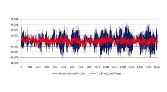
The level of this unwanted motion is called the noise floor. A noise floor is the ambient level of disturbance in a system. When measuring features it is imperative to be able to observe this noise floor and understand how it affects your measurement and how precise the measurement can be. It is always best to look at the noise floor with and without the servos active. This gives a picture of natural vibrations versus servo-induced vibrations.

Figure 1. Position jitter showing servo versus floor vibration in µm.
The noise floor is affected by jitter in the motion system, ground floor vibrations, and drive jitter to name a few of the more common culprits. A servo loop is used to correct for any errors in positioning, an air isolation system is used to minimize ground floor vibrations, and current loop control is used to minimize drive induced jitter. Aerotech’s X-drives solve two of the three vibration sources.
To achieve a lower noise floor you can increase the current loop resolution, which gives the ability to have smaller current steps and increases the servo loop rate, which will “see” this vibration faster and be able to compensate for it sooner. Our newest drive hardware has implemented both of these features and we have seen a reduction of the noise floor by two to four times over older drive technology. This in-position stability is critical while taking measurements or triggering an operation while the part is in situ.

Figure 2. X-Series linear servo induced jitter, 10 nm pk-pk.
Since the new servo hardware has 2-4X less noise it may be possible to get away from more expensive linear amplifierbased drive hardware and use economical Pulse Width Modulated (PWM) hardware. For applications that used to require the less efficient, costlier and bulkier linear amplifiers, PWM amplifiers may now be a possibility. This can minimize cabinet space and lower the cost of the finished machine. PWM drives are up to 40% less expensive than their linear counterparts and over four-times smaller in their overall volume and weight. PWM drives generate less heat than linear drives and can operate at higher power ratings. Where linear drives were utilized purely for in-position requirements, the PWM X-drives are an economical option and a true upgrade. This is a win-win in the truest sense with better performance at a lower cost.
Analog Noise and Data Rate Bottlenecks
The majority of positioning systems require some type of feedback to accurately sense system position. The control system uses this information to generate an error signal. The control loop makes a determination based on this signal so that it can compensate for this error. Typically encoders are chosen for this purpose. Incremental encoders typically come in two flavors– digital or analog. Analog versus digital debates have been going on since the first compact disc was released in the 1980s. Digitizing a signal removes fidelity and takes a true sinusoid and turns it into a staircase. Optical encoders are still analog, but this signal gets digitized either in the encoder electronics or at the drive end. Drives that take analog feedback signals eventually digitize these signals internally. The higher the interpolation value on these analog signals the closer to a pure sinusoid you will get.

Figure 3. ADC noise reduction
In the same vein as the noise floor previously mentioned, the analog encoder signals themselves will have a noise floor. To minimize this noise, filtering techniques are used. The higher you can sample the analog encoder, the more the drive electronics can oversample and filter this signal to remove this noise. Figure 3 shows the results of this increased sampling rate. Since this noise is directly related to position jitter we can see an improvement of 100X over older drives!
Another benefit to this higher sampling rate is an increase in speed. A drive can only read so many counts per second – the higher the sampling rate the more counts per second we can read. Encoder manufacturers come up with finer pitch scales every year that are affected by a drive’s maximum input rate. Moving from a 40 µm pitch scale to a 4 µm pitch scale results in 10X lower potential max positioning speed if the drives are not also upgraded to read these scales faster. The X-Series drives have 4X the encoder input rate when compared to their predecessors.
Since higher performance is always the goal of a new design, utilizing analog encoders with the X-drives creates an environment where you can utilize a robust controls package to minimize audible noise and maximize velocity stability.
Conclusion
Let the design phase be your opportunity to look for partners who are willing to work with you to get the most out of your new machine. Picking the wrong servo drives could limit the overall performance of the machine. Improved communication reliability, positioning accuracy, and encoder sampling built into a proven drive technology that is reliable, robust, and performance-enhancing is the safe choice when designing your next system that will drive your company’s growth into the future.