
Source : Mouser Electronics
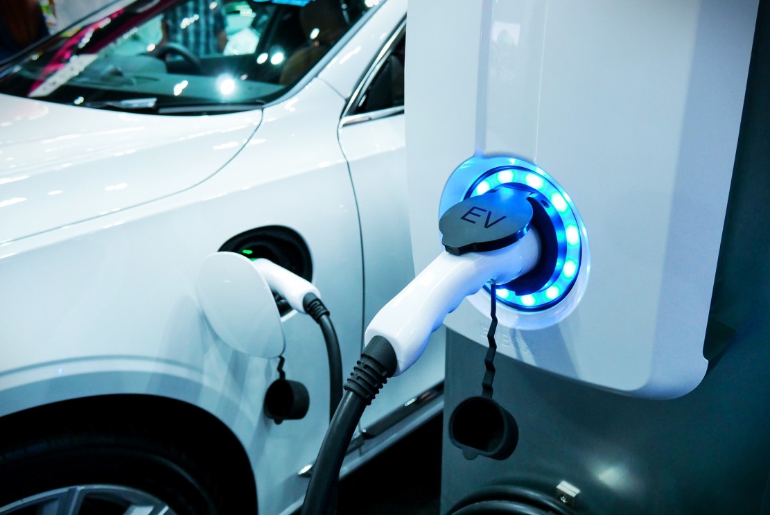
Governments around the world are pushing both private and commercial vehicle owners toward environmentally cleaner alternatives, such as electric vehicles (EV). However, one of the biggest hindrances to making this change is vehicle range concerns. The majority of low- to mid-range EVs can complete several journeys before recharging is required. But, if you’re planning a longer trip, EV charging en route still requires more time than refueling a combustion engine vehicle.
The industry is working hard to improve charging times by developing fast DC charging solutions that are comparable with refueling a combustion engine vehicle. Unlike the EV’s onboard charger (OBC) that uses household AC, fast DC chargers circumvent the OBC to deliver energy directly to the EV’s battery charging circuitry. And, unlike their AC counterparts, such chargers can charge an EV to 80 percent range in as little as 10 minutes.
Fast DC Chargers for EVs
Current fast DC chargers deliver between 35kW and 50kW, operating at up to 800V. The highest power delivery chargers are typically installed at highway service stations. Whether your EV can sink such power depends on its design and batteries. Most of today’s EVs are limited to charging levels below 300kW.
There are plenty of engineering challenges for such a high power and voltage application. These range from safety and reliability, to serviceability, efficiency, size, and cost—both operating and acquisition. To date, the design approach has relied upon silicon IGBTs and MOSFETs. However, thanks to the introduction of wide bandgap semiconductors, such as Silicon Carbide from Wolfspeed, Silicon Carbide MOSFETs are rapidly becoming the preferred choice of power switch.
The Move to Silicon Carbide MOSFETs for EV Chargers
The core of a fast DC charger can be broken down into two key blocks:
- The AC/DC stage, converting incoming AC to a DC link voltage
- A DC/DC converter that supplies DC to the EV’s batteries.
In addition, there are also payment mechanisms, a human-machine interface, and connectivity elements. The power delivery section of such chargers is constructed of several modules, with each module typically contributing somewhere between 15kW and 50kW to the total power.

Figure 1: Simplified block diagram of the power converters for an EV fast DC charger. (Source: Wolfspeed)
Highest possible efficiency and power density are key design targets, enabling engineers to deliver smaller and lighter modules with fewer heat dissipation challenges.
Active Front End with Wolfspeed Silicon Carbide MOSFETs
For the AC/DC stage, the Active Front End (AFE) is a common topology implemented using six silicon IGBTs with a switching frequency of 20kHz. Such a 22kW AFE stage would be expected to achieve a respectable peak efficiency of 97.2 percent. However, the power density lies at around 3.5kW/L, with thermal design elements responsible for 20 percent of the system cost.
This is why designers are moving to Silicon Carbide-based designs. Compared to silicon-based alternatives, the RDS(ON) of Silicon Carbide MOSFETs increases less with increasing temperature. With a lower RDS(ON) than silicon at the application’s operating temperature, heat dissipation is lower. Devices such as the Wolfspeed 1200V CCB021M12FM3 in Wolfspeed WolfPACK™ Power Modules, with 21mΩ Silicon Carbide MOSFETs, are an excellent choice for an AFE topology.
Such Silicon Carbide MOSFETs also operate at higher switching speeds of up to 45kHz, enabling a smaller choke to be used compared to an IGBT-based AFE. Additionally, thanks to the resultant reduction in dissipated heat, the costs for heat dissipation are just 10 percent of the overall system cost.

Figure 2: A 25kW bi-directional AC/DC AFE featuring Wolfspeed WolfPACK™ power modules suited to fast DC charger designs. (Source: Wolfspeed)
A 25kW AFE reference design suited to fast DC charger applications, CRD25AD12N-FMC, is also available. Thanks to the Wolfspeed WolfPACK™ three-phase configuration modules used, this bi-directional design attains a peak efficiency of 98.5 percent and power densities of >4.6kW/L.
From Silicon MOSFET to Silicon Carbide in DC/DC Stage
Silicon Carbide is also taking over from silicon in the DC/DC stage. Silicon-based switches operating at around 100kHz in DC/DC resonant LLC converters can attain peak efficiencies of 97.5 percent and power densities of 3.5kW/L. However, the power requirements typically demand an interleaved design, which increases the component count and complexity.
By moving to a Silicon Carbide MOSFET design with discrete devices such as the Wolfspeed C3M0032120K switching speeds can be increased to up to 250kHz. These four-pin TO-247-4 packaged Silicon Carbide MOSFETs also offer a Kelvin pin. In hard-switched, high current, and high frequencies topologies, this helps to reduce crosstalk and switching losses. As a result, these losses can be up to four times lower when compared to the use of three-lead Silicon Carbide devices. A resonant CLLC reference design, CRD-22DD12N, uses just eight discrete Silicon Carbide MOSFETs in a design for a 22kW bi-directional DC/DC converter. As part of a fast EV charger design, it can achieve peak efficiencies beyond 98.5 percent at power densities of 8kW/L.

Figure 3: This bi-directional DC-DC reference design leverages the performance of Wolfspeed’s C3M0032120K discrete Silicon Carbide MOSFETs. (Source: Wolfspeed)
Silicon Carbide for Fast DC Charger Applications
As the user base for EVs grows in the coming decade, so will the demand for faster ‘refueling’ speeds. Wide bandgap materials, such as Wolfspeed Silicon Carbide MOSFETs, are the solution, offering lower losses, dissipating less heat, and enabling higher power densities than equivalent designs relying on silicon power device technology.
To learn more, visit www.mouser.com